

- Products
- Cryo Gate Valves
- Cryo Gate Valves
- Cryo Gate Valves
- Cryo Gate Valves
- Cryo Gate Valves
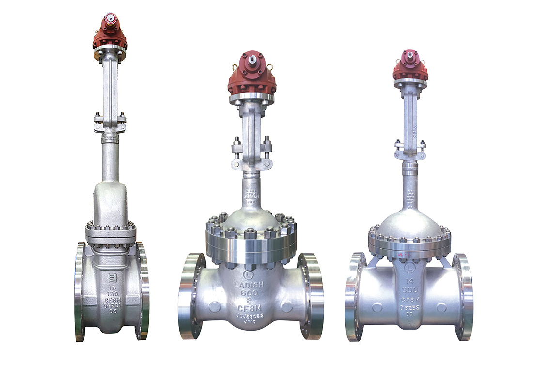
Cryogenic Gate ValvesCast Stainless Steel Bolted Bonnet
■ Basic design : API 603, API 600, ASME B16.34, MS-SP134, BS6364, Intergral seat type
■ Flange drilling : ANSI B16.5 (2″~24″)
■ Face to face : ANSI B16.10
■ Test : API 598
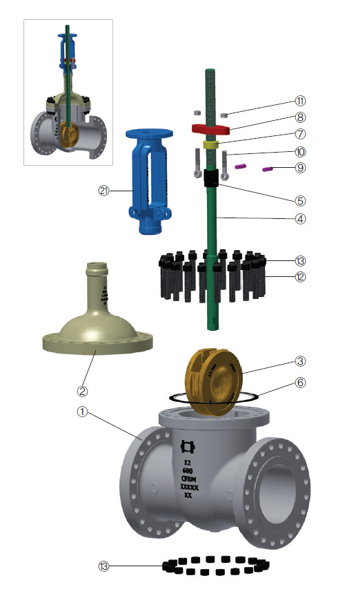
① BODY The body is in cast stainless steel and is carefully designed in all its details.
The basic dimension,i.e.wall thickness, face to face and flanges comply with the relevant API and ANSI standards.
The sealing surfaces for connection to the bonnet are flat finish in the 150lb Class, recessed in the 300lb, 600lb Class or may be ring joint in the 900lb Class and above.
Bosses may be provided for drain taps or by-pass piping.
② EXTENDED BONNET The extended bonnet is in stainless steel.
It is machined to accept the yoke sleeve and incorporates a stuffing box dimension in accordance with the API standard.
③ DISC The disc is part of the trim. It is normally supplied as flexible.
It is connected to the stem by means of a T-joint.
The guides on each side of the disc are casted for proper alignment with the body guides.
Special attention is given to the seating surface which are ground and lapped to insure a perfectly tight seal.
④ STEM The stem is part of the trim. A stem is provided with a T-head.
A ground backseat is provided to ensure perfectly tight seal to the stuffing box when the valve is fully open.
The stem is ground to minimize friction and prevent damage to gland packing.
The threading is trapezoidal ACME type.
Dimensions comply with the applicable standard.
⑭ YOKE SLEEVE The yoke sleeve is made from stainless steel or ductile iron having high resistance to wear and a high melting point.
It is designed to permit removal from the bonnet or the yoke while the valve is in service.
Gate valves 6” 600lb Class and above are fitted with a ball thrust bearing.
⑫, ⑬ BONNET BOLT/NUT Bonnet studs and nuts are manufactured from alloy or stainless steel to the relevant ASTM standard.
⑯ HANDWHEEL The steel or nodular iron handwheels are well shaped and large enough to give ease of movement when operating the valve, even under maximum differential pressure.
■ Flange drilling : ANSI B16.5 (2″~24″)
■ Face to face : ANSI B16.10
■ Test : API 598
① BODY The body is in cast stainless steel and is carefully designed in all its details.
The basic dimension,i.e.wall thickness, face to face and flanges comply with the relevant API and ANSI standards.
The sealing surfaces for connection to the bonnet are flat finish in the 150lb Class, recessed in the 300lb, 600lb Class or may be ring joint in the 900lb Class and above.
Bosses may be provided for drain taps or by-pass piping.
② EXTENDED BONNET The extended bonnet is in stainless steel.
It is machined to accept the yoke sleeve and incorporates a stuffing box dimension in accordance with the API standard.
③ DISC The disc is part of the trim. It is normally supplied as flexible.
It is connected to the stem by means of a T-joint.
The guides on each side of the disc are casted for proper alignment with the body guides.
Special attention is given to the seating surface which are ground and lapped to insure a perfectly tight seal.
④ STEM The stem is part of the trim. A stem is provided with a T-head.
A ground backseat is provided to ensure perfectly tight seal to the stuffing box when the valve is fully open.
The stem is ground to minimize friction and prevent damage to gland packing.
The threading is trapezoidal ACME type.
Dimensions comply with the applicable standard.
⑭ YOKE SLEEVE The yoke sleeve is made from stainless steel or ductile iron having high resistance to wear and a high melting point.
It is designed to permit removal from the bonnet or the yoke while the valve is in service.
Gate valves 6” 600lb Class and above are fitted with a ball thrust bearing.
⑫, ⑬ BONNET BOLT/NUT Bonnet studs and nuts are manufactured from alloy or stainless steel to the relevant ASTM standard.
⑯ HANDWHEEL The steel or nodular iron handwheels are well shaped and large enough to give ease of movement when operating the valve, even under maximum differential pressure.
※ If you do not see it all, drag the table to the left or right.
| No | Name of Part | ASTM specification | |||
|---|---|---|---|---|---|
| Cast Stainless steel | |||||
| 1 | BODY | A351 CF8 | A351 CF3 | A351 CF8M | A351 CF3M |
| 2 | BONNET | A351 CF8 | A351 CF3 | A351 CF8M | A351 CF3M |
| 3 | DISC | A351 CF8 | A351 CF3 | A351 CF8M | A351 CF3M |
| 4 | STEM | A276 304 | A276 304L | A276 316 | A276 316L |
| 5 | PACKING | TEADIT / PILLAR | TEADIT / PILLAR | TEADIT / PILLAR | TEADIT / PILLAR |
| 6 | GASKET | COMMERCIAL | COMMERCIAL | COMMERCIAL | COMMERCIAL |
| 7 | GLAND RING | A276 304 | A276 304L | A276 316 | A276 316L |
| 8 | GLAND FLANGE | A351 CF8 / A240 304 | A351 CF8 / A240 304 | A351 CF8 / A240 304 | A351 CF8 / A240 304 |
| 9 | HINGE PIN | A276 304 | A276 304 | A276 304 | A276 304 |
| 10 | HINGE BOLT | A193 B8 | A193 B8 | A193 B8 | A193 B8 |
| 11 | HINGE NUT | A194 8 | A194 8 | A194 8 | A194 8 |
| 12 | BONNET BOLT | A193 B8 | A193 B8 | A193 B8 | A193 B8 |
| 13 | BONNET NUT | A194 8 | A194 8 | A194 8 | A194 8 |
| 14 | YOKE SLEEVE | A439 D2C | A439 D2C | A439 D2C | A439 D2C |
| 15 | SLEEVE NUT | A276 304 | A276 304 | A276 304 | A276 304 |
| 16 | HANDWHEEL | A536 60 | A536 60 | A536 60 | A536 60 |
| 17 | HANDLE NUT | A276 304 | A276 304 | A276 304 | A276 304 |
| 18 | SET BOLT | A194 B8 | A276 304 | A276 304 | A276 304 |
| 19 | GREASE NIPPLE | A307 B | A307 B | A307 B | A307 B |
| 20 | BEARING | 52100 | 52100 | 52100 | 52100 |
| 21 | YOKE | A351 CF8 | A351 CF3 | A351 CF8M | A276 316L |
※ Note. - Packing & gasket material ; customer's requirements